![]()
Home About Basics Casts Theory Verification
References
Contact
Basics
Purpose
The purpose of this section is to give basic
introductions to:
· Fly casting mechanics.
· How the simulation model works.
Fly casting
Fly casting may be described as casting a
nearly massless fly using a weighted fly line. Air drag-forces work against the
fly line moving in the casting direction. Hence, limiting air drag is the key
to making long casts and to reducing the effort involved in casting. Efficient
fly casting can be thought of as the art of minimizing air drag.
Local line velocities on a fly line loop,
travelling to the left, are shown in the figure below:
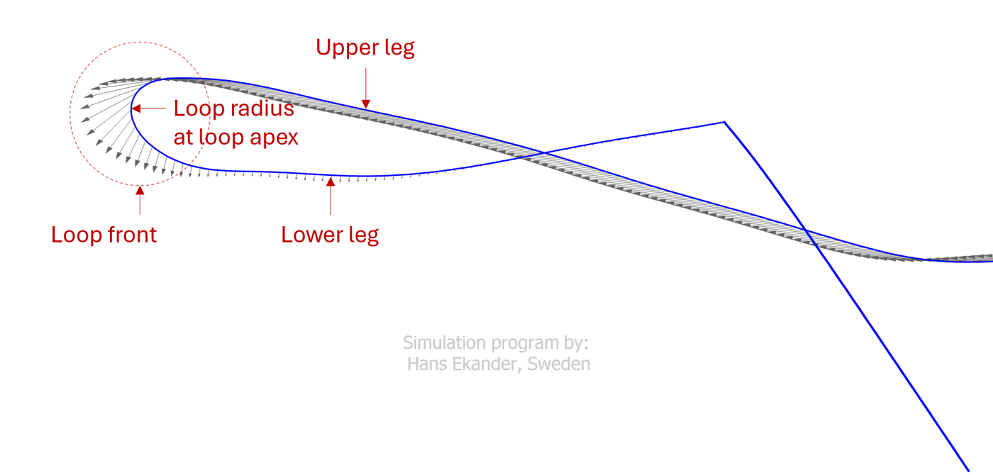
The figure above shows that the line velocity
is high in the upper leg and low in the lower leg. It also shows that the
normal/transverse velocity is large in the loop front region.
Air drag on the fly line is shown in the
figure below:
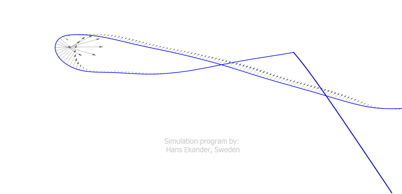
Normal air drag is about 50 times higher than
axial drag for equal normal and axial velocities. This is shown in the figure
above by the large drag forces in the loop front region. One way of reducing
the total air drag force on a loop is to reduce the loop front radius. A narrow
loop with a small radius will have less air drag and travel farther, in
particular if moving against the wind. Also, it is desirable to keep the upper
leg as straight as possible to minimize normal drag.
The way in which the line is accelerated in
the casting stroke has a strong impact on the loop shape. Ideally, the force
accelerating the line shall be applied in the direction of the fly line (which
ideally shall be straight before the acceleration starts) and along a straight
path. The path along which the force is applied is the path the rod tip travels
during the casting stroke. Therefore, the rod tip path is one of the keys to
efficient fly casting. Expert casters have developed the ability to apply the
casting stroke in a manner giving almost straight rod tip paths, which in turn
gives narrow loops, which in turn gives long/efficient casts.
Simulation model
The simulation model provides possibilities
to study the impact of changing “one thing at a time” and to test “new ideas”.
Also, it provides detailed output that may be very difficult to measure.
My simulation model is briefly described in
this section with an emphasis on what one has to put in (input) and what one
gets out from it (output).
The simulation model is 2D continuum-based
and solves the coupled problem of rod and line dynamics. It is based on
Newton’s 3 laws of motion:
1. A body remains at rest, or in motion at a constant speed in a
straight line, unless it is acted on by a force.
2. The net force on a body is equal to the body's acceleration
times its mass.
3. When two bodies interact, they apply forces to one another that
are equal in magnitude and opposite in direction.
For further details, see Theory.
Input to the simulation model is summarized as follows:
· What the caster does. This is
referred to as boundary conditions and describes versus time:
o Angular motion i.e., how the caster rotates the rod handle.
o Translational motion i.e., how the caster moves the rod handle
in horizontal and vertical directions.
o Double haul i.e., how the caster applies double haul (if so).
· What equipment is used. The following
data are given to describe the rod, fly line and
leader (on all points along the length):
o The outer diameter.
o The mass density i.e., the mass per unit length.
o Bending stiffness i.e., the resistance to bending.
o Material damping i.e., how strain/bending energy is
dissipated/lost.
Output data that can be studied once a simulation has been completed
is summarized below:
· Solution variables. Angle,
curvature, vertical velocity, horizontal velocity, tensile force and normal
force are known for all points in time and at all points in space i.e., at all
points along rod and line.
· Energies and work. Kinetic,
potential and strain/bending energies are known at each point in time and for
each part of equipment e.g., rod, fly line, leader and fly. The accumulated
work from the start is also known at each point in time and for each part of
equipment. Work is available in the following categories: work done by the
caster, dissipation/losses by air drag and dissipation/losses by material
damping.
· Cast specifics. Some concepts
used among fly casters are also available at each point in time including:
o Rod tip path/trajectory i.e., the curve the rod tip would draw
on paper were a pen attached to it.
o Rod bend/deflection i.e., how much the rod tip is deflected in
the normal direction (compared to an infinitely stiff rod).
o Rod straight position, RSP, i.e., the position on the rod tip
path where rod bend is zero.
o Loop apex speed and loop apex radius.
o Line tensile force at rod tip.
o Bending moment at rod handle, providing information of the
required wrist strength of the caster.
o …