![]()
Home About Basics Casts Theory Verification
References
Contact
50ft oh cast, reference
Purpose
The purposes of this section are to
illustrate:
· Input defining the casting stroke: angular and translational
motions.
· Input defining the equipment: rod, line and fly.
· How simulated casts are animated.
· Additional output data of relevance.
At the bottom of this page some of the
applied notation is explained.
Input, casting stroke
The casting stroke, i.e. the action by
caster, provides input to the simulation model. The casting stroke refers to
rod rotation, rod translation and line haul (if present).
The rod rotation at the handle for the 50ft
ref. cast is shown below with the angle (in relation to the horizontal) and the
angular velocity versus time:
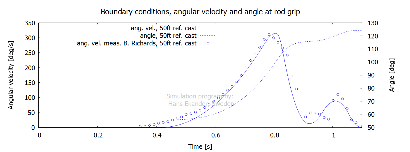
Notes:
· “Acceleration phase” refers to the time with increasing angular
velocity, 0.42 to 0.81 s, above.
· “Deceleration phase” refers to the time with decreasing angular
velocity, 0.81 to 0.92 s, above.
· The time from 0.92 to 1.10 s above, is referred to as “rebound
and counter flex”.
· The angle and the angular velocity given as input have been set
to approximately match a measured 50ft cast by the expert caster Bruce
Richards.
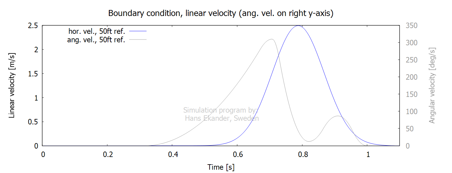
In addition to rod rotation, the rod is
usually subject to translational motion and in some cases also to line haul.
The translation may be both horizontal and vertical. The casting stroke for
this 50ft ref. cast is subject to horizontal translation only. The horizontal
velocity (linear in contrast to the angular velocity) is shown with the angular
velocity as reference below:
Input, equipment
The input data used to model a modern, fast,
“high end” 5wt rod is presented below. The model has been verified through
comparisons with experiments, see Verification
of fly rod. If not stated explicitly, the rod model
below is used in all simulated 50ft casts.
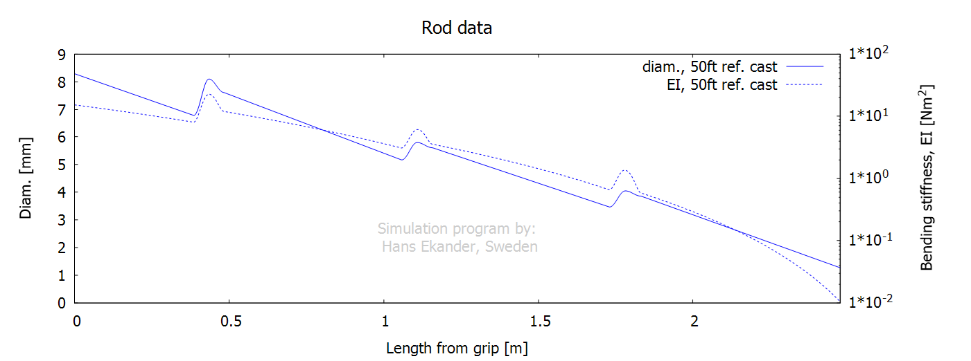
The fly rod blank is modeled for each rod
section as a hollow tapered tube with a Young’s modulus and density varying
linearly along each section. Each ferrule gives an
increase in local bending stiffness. The outer rod diameter and the bending
stiffness are presented below. Note that the outer diameter is mapped on the
left axis and the bending stiffness on the right axis using a logarithmic
scale.
The guides (including thread & glue) give
additions to the rod mass density with the relative impact being largest for
the top section. The mass density for the guides is added to the mass density
of the blank to give the rod mass density, see plot below:
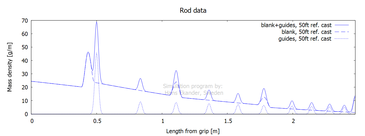
Note: When casting, the fly line is retained
to the fly rod by the guides. Therefore, the mass density of the fly line is
added to the mass density of the rod in all simulated casts.
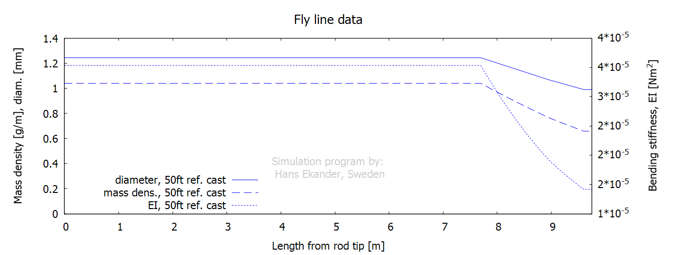
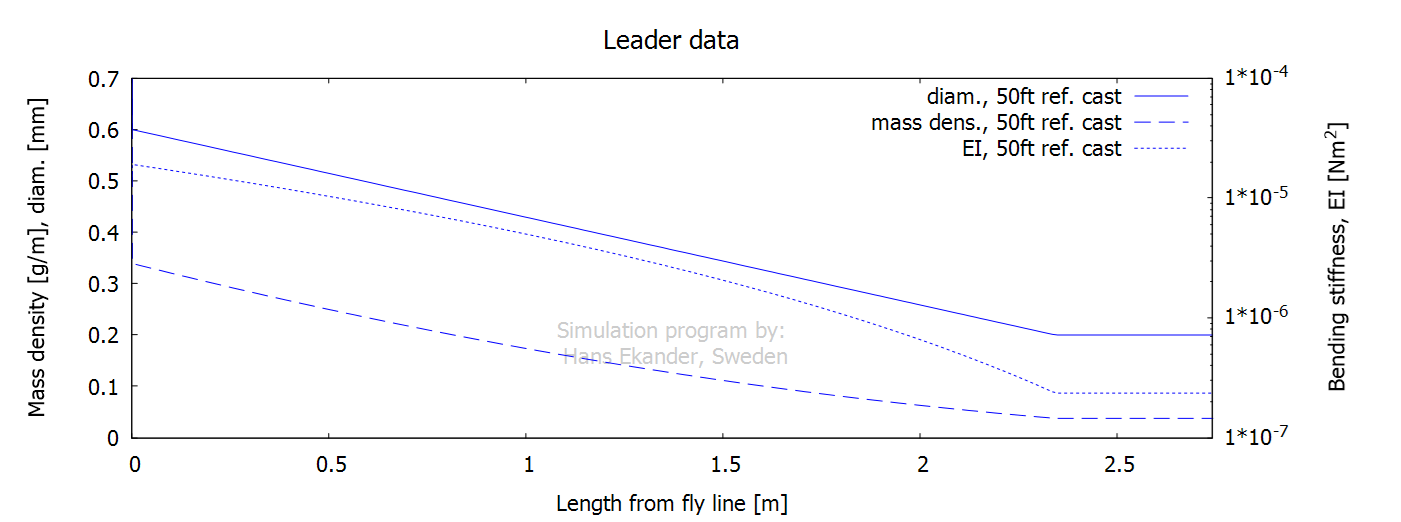
Below, the input data for the fly line and
the leader (including tippet) are presented. Note that the bending stiffnesses are
mapped on the right axes and that a logarithmic scale is used for the leader.
The fly attached at the end of the tippet is
given a mass of 48 mg and drag giving a terminal
velocity of 2.5 m/s at free fall.
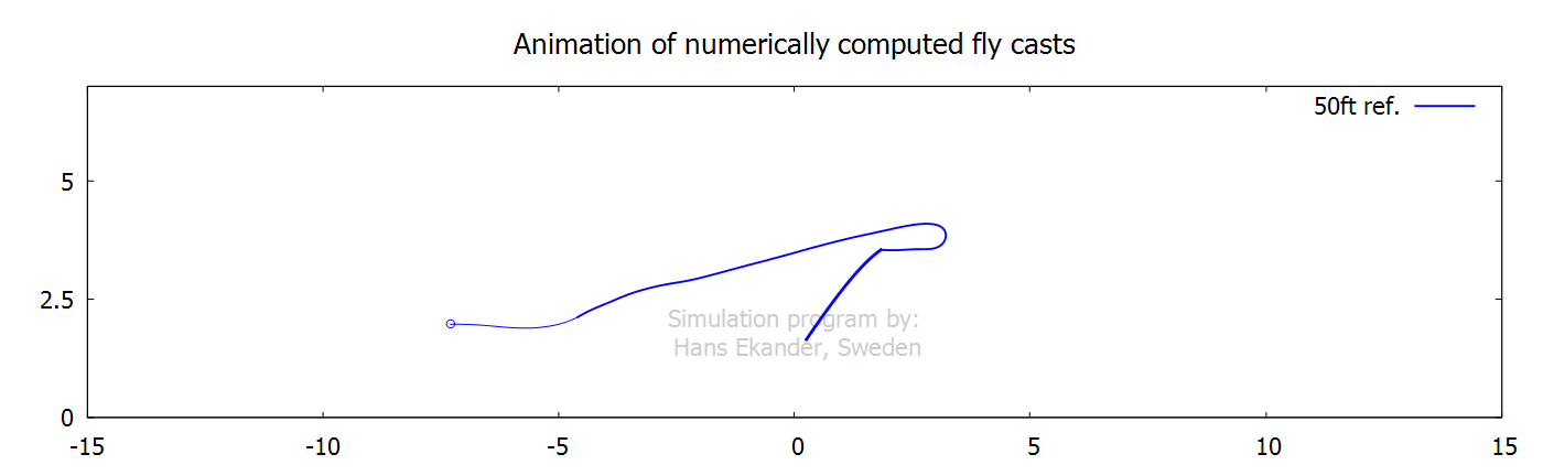
Output, animations
Click on the graphs below to start animations.
Note that animations are shown in slow motion.
The animation below includes an infinitely
“stiff rod” showing the rod handle movement.
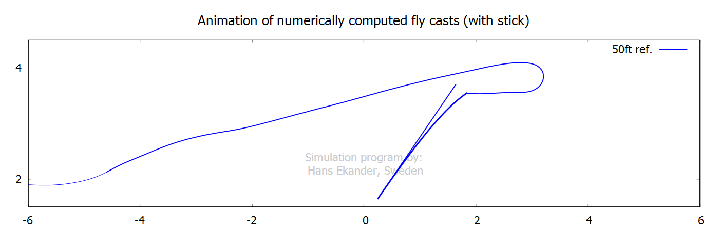
The application of angular and translation velocities for the
50ft ref. cast is considered smooth. This contributes to an upper leg with
limited normal air drag and wiggles. The “stiff rod” is shown “aligned with the
rod handle” and shows how the rod would move if it were infinitely stiff.
Output, graphs
The graphs below are shown for one stroke
(50% of a complete casting cycle).
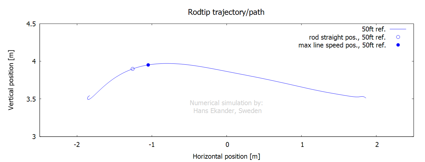
The rod tip trajectory is the path the rod
tip travels (impacts loop shape). Also, shown are rod straight position (zero
rod tip deflection), position of max line speed at the rod tip (value is given above
the point) and position for loop start (defined as the position where the line
at the rod tip is vertical). Notes:
· In the graph above the casting direction is to the left i.e.,
the stroke starts with the rod tip to the right.
· An excessively curved path leads to wide loops (high air drag).
· A “local dip” in the rod tip path may generate a tailing loop
(and line tangle).
· The vertical difference between the points “max line speed” and
“loop start” reflects the loop width.
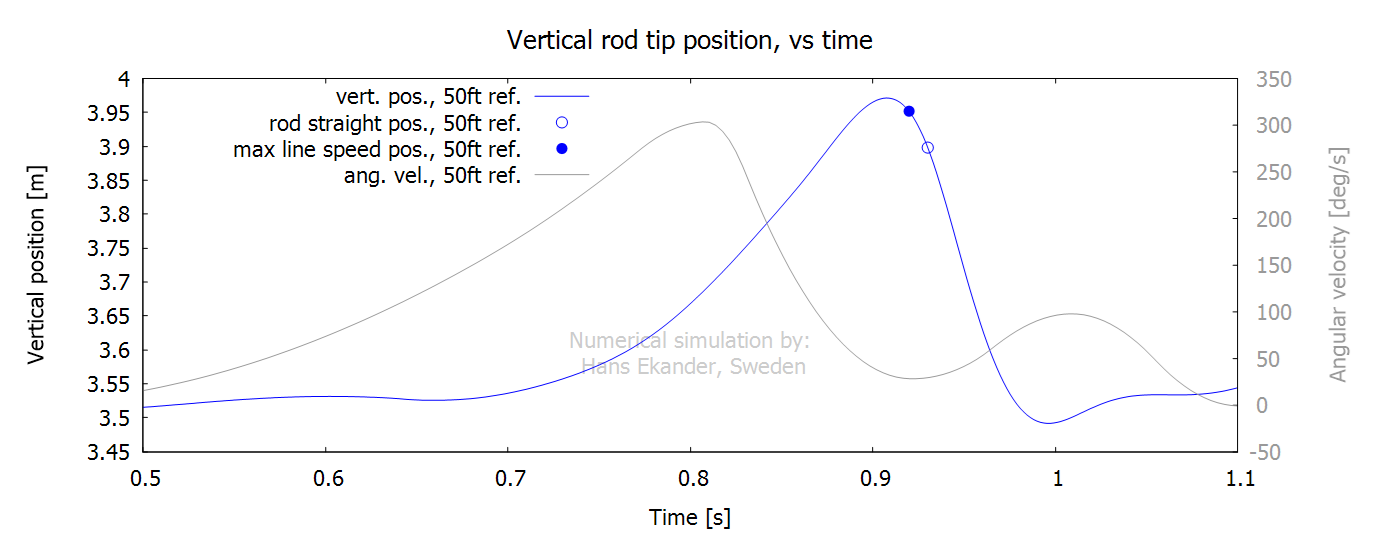
Below, the positions are shown versus time
compared with the angular velocity at the rod handle.
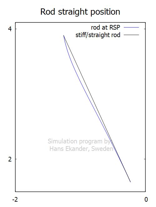
It is worth remarking on the concept of rod
straight position, RSP. It is defined as the point with zero rod tip bend/deflection
normal to a stiff/straight rod, but the term RSP is misleading in the sense
that the rod isn’t straight. The rod shape for the cast presented in this
section at the point of zero rod tip deflection is shown in the plot below:
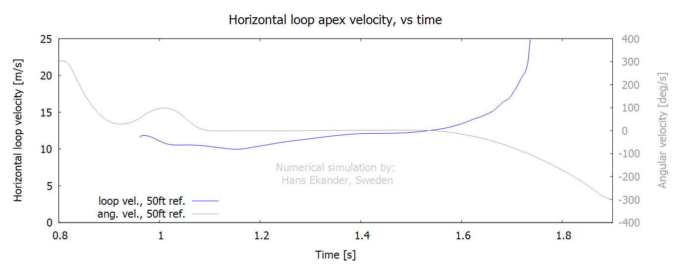
The horizontal loop velocity is the velocity
of the leading edge of the fly line loop. Notes:
· The loop starts to propagate when the fly line moves “ahead” of
the rod tip.
· The time window for the loop velocity differs from the other
time plots below.
The radius of
curvature of the fly line at the loop apex is shown below. Note:
· A larger radius indicates a wider loop (and larger normal air
drag).

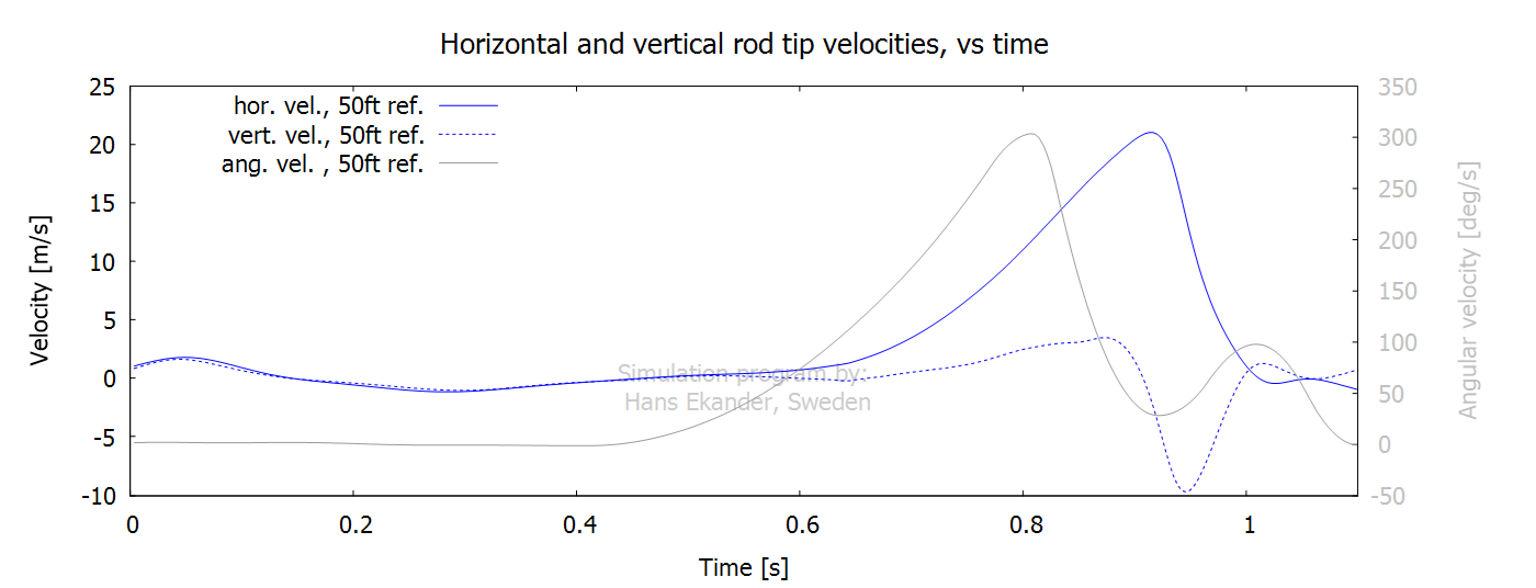
The horizontal and vertical rod tip velocities equal the respective
line velocities at the rod tip if no line haul/feed.
The rod tip speed is the absolute value of the velocity. It also
equals the line speed at the rod tip if no line haul/feed
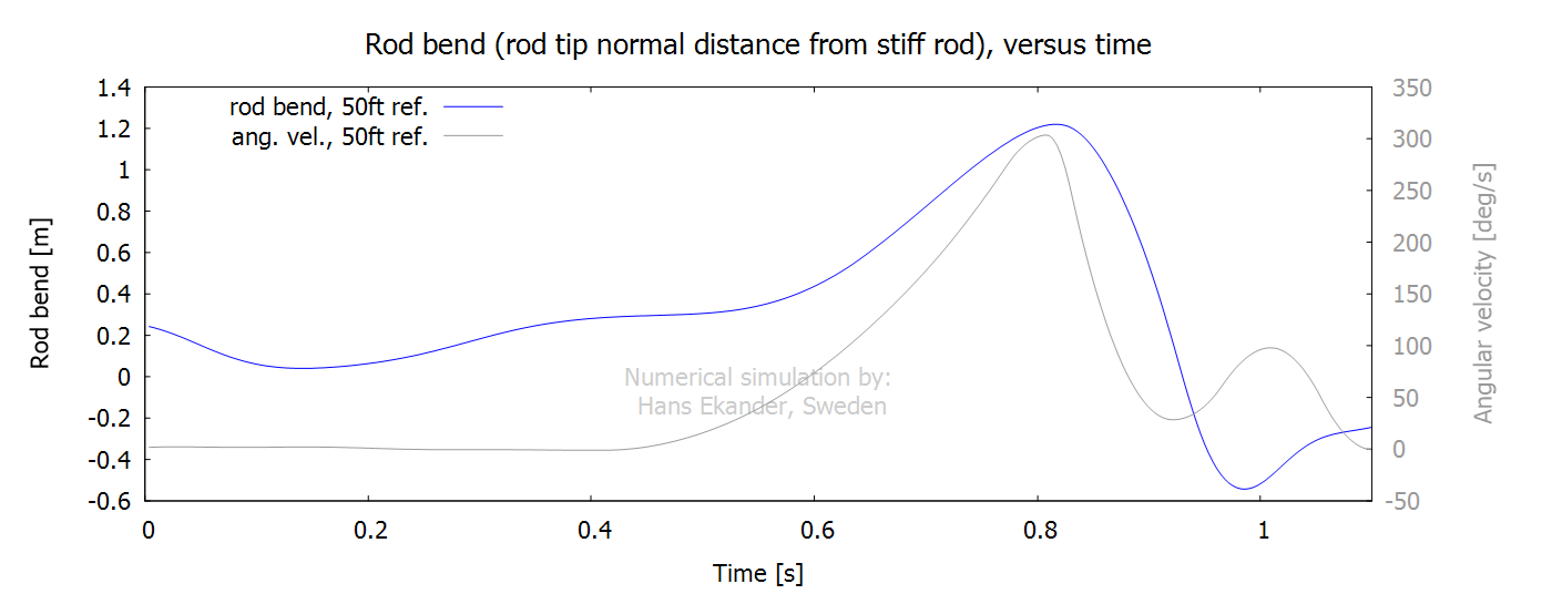
The rod bend is a measure of the rod tip
deflection. It is defined as the normal distance from an infinitely stiff rod
to the rod tip.
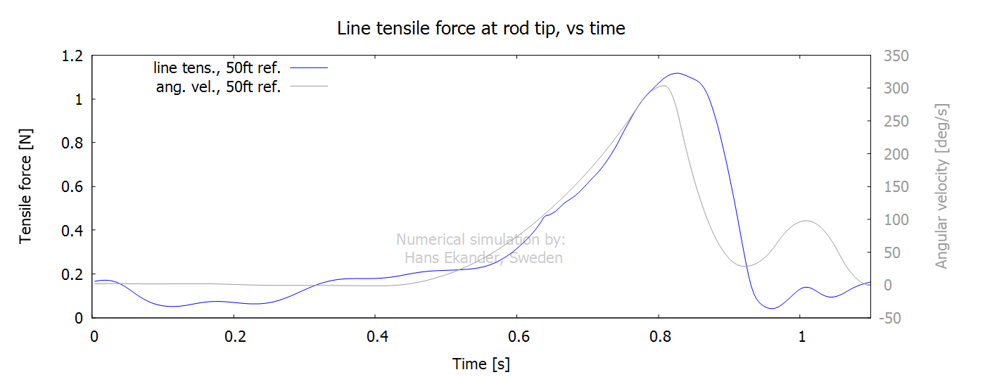
The line tensile force at rod tip is the
internal line force accelerating the line.
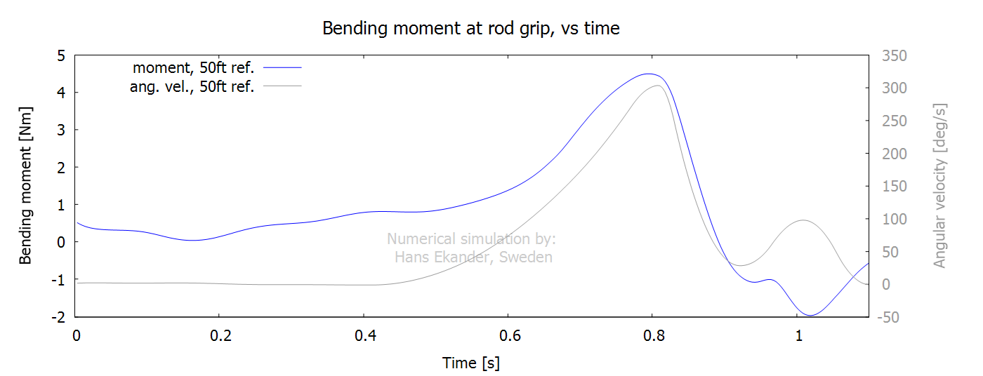
The bending moment at the rod handle gives an
approximate measure of the wrist strength required by the caster. Notes:
· The bending moment in the graph below is defined at the
interface between blank and handle.
· The caster’s grip is “at the handle”, so the applied bending
moment by the caster isn’t exactly as the curve below.
Two forces are working to “keep the line in
the air” in this cast:
1. The vertical component of the air drag.
2. The vertical component of the tensile line force at the rod tip.
The plot below shows the vertical forces working
to keep the line (incl. leader and fly) in the air
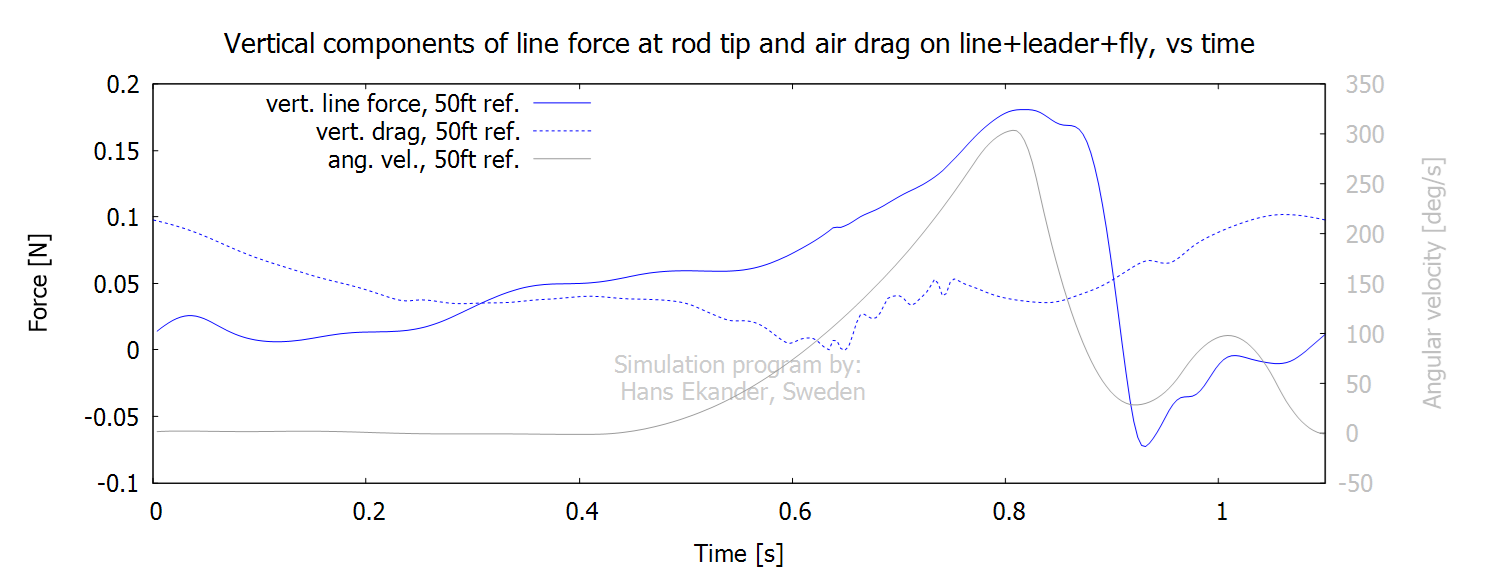
Notes:
· The time average for the vertical air drag force is about 49% of
the gravity force.
· The time average of the vertical line force is about 51% of the
gravity force.
· See also the vector plot of air drag force below.
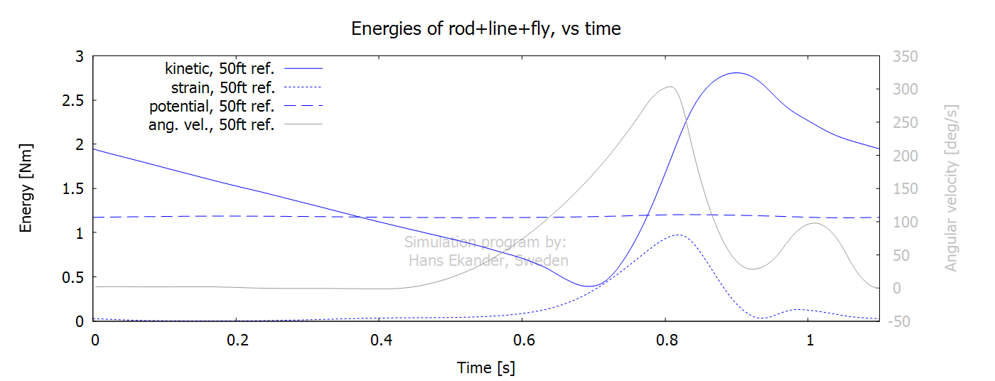
Output, energies and work
The mechanical energy in the system (here
e.g.: rod+line+fly) has the following components, see
the Theory section for exact definitions and “Notation” below:
1. Potential energy which is the sum/integral of the gravity force
times the elevation.
2. Kinetic energy which is the sum/integral of the mass times the velocity
squared / 2.
3. Strain energy which is the energy stored (mainly in the rod) due to bending. It is the sum/integral of the bending
stiffness times the curvature squared / 2.
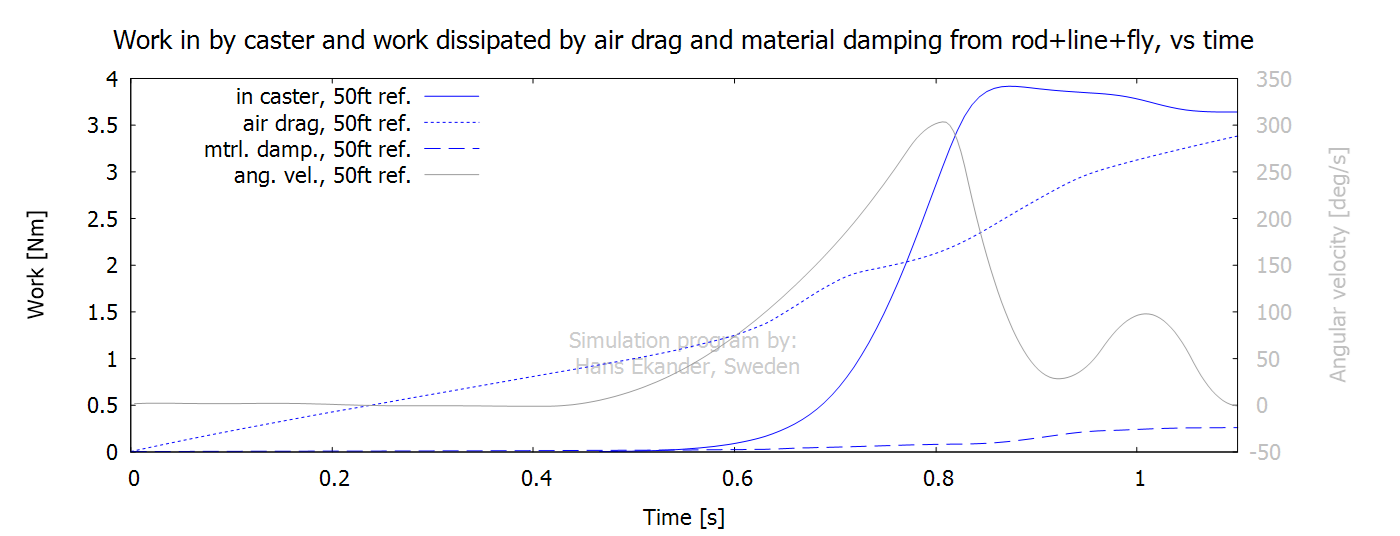
If no work is done on the system, then the
conservation of mechanical energy requires that the sum of the three energy
components listed above remains constant. However, if
work is done on the system, then the sum of the energies will change. Here,
three kinds of work are present, see the Theory section for exact definitions:
1. Work by the caster. The caster does work both due to rotation
and translation of the rod handle (and due to haul, if present).
2. Work by air drag forces. Air drag is always acting to decrease
the energy in the system and is referred to as loss/dissipation.
3. Work by material damping is always acting to decrease the energy
in the system. Here, material damping is present when the curvature/bending
changes (mainly in the rod).
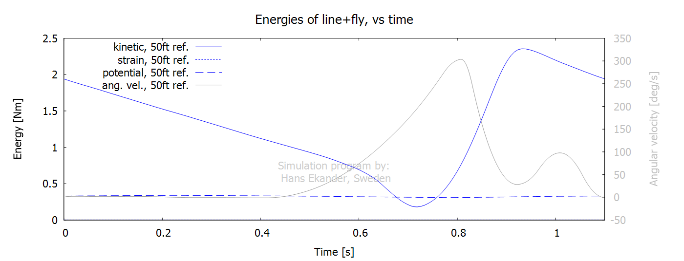
The energies presented below include rod+line+leader+fly. Note:
· For symmetric casts, as the one shown here, the energies at the
start and end of each stroke are equal.
The cumulative work (from start) by fluid drag and material damping, presented below, include rod+line+leader+fly. Notes:
· The sum of the accumulated dissipated work by air drag and material damping equals the accumulated work input
by the caster at the end of the stroke. Hence, the net work
done on the system is zero, consistent with the energy being the same at the
start and end of the symmetric cast.
· Mechanical work in by the caster decreases at the end of the
stroke. The accumulated muscular effort, however, increases throughout the
entire stroke.
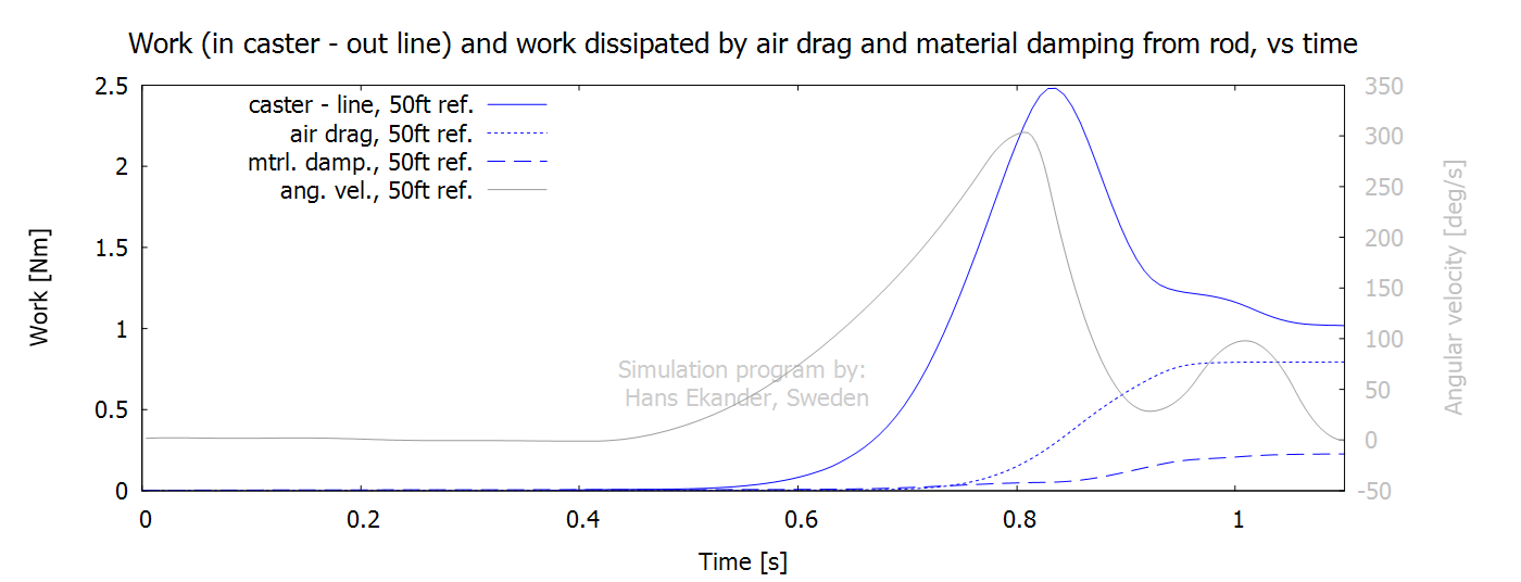
The energies for the rod only are presented
below.
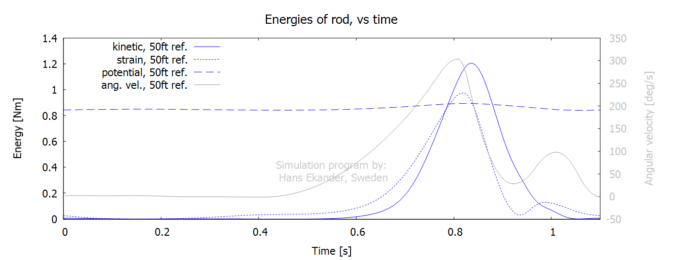
The cumulative work (from start) for the rod
only by fluid drag and material damping are shown below. Note:
· “caster-line” is the accumulated work
input by the caster minus the accumulated work done by the rod on the fly line
(at the rod tip).
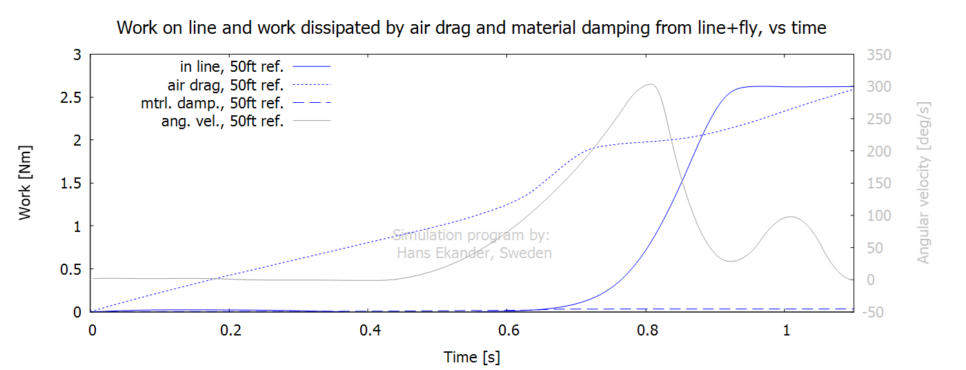
The energies for the line (incl. leader) and
fly are presented below.
The cumulative work (from start) for the line
(incl. leader) and fly by fluid drag and material damping are shown below.
Note:
· “in line” is the accumulated work done
by the rod on the fly line (at the rod tip).
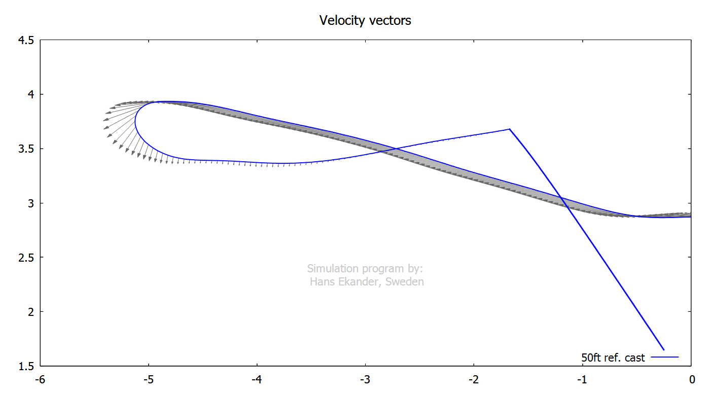
Output, vectors
The vector plot below shows the local
velocity when the loop has propagated about a rod length. Note that the loop
front velocity is not identical with the line velocity.
The vector plot below shows the local air
drag force per unit length. Notes:
· The axial air drag is only about 2% of the normal air drag (for
equal axial and normal velocities).
· The integrated air drag generates a net “lift”.

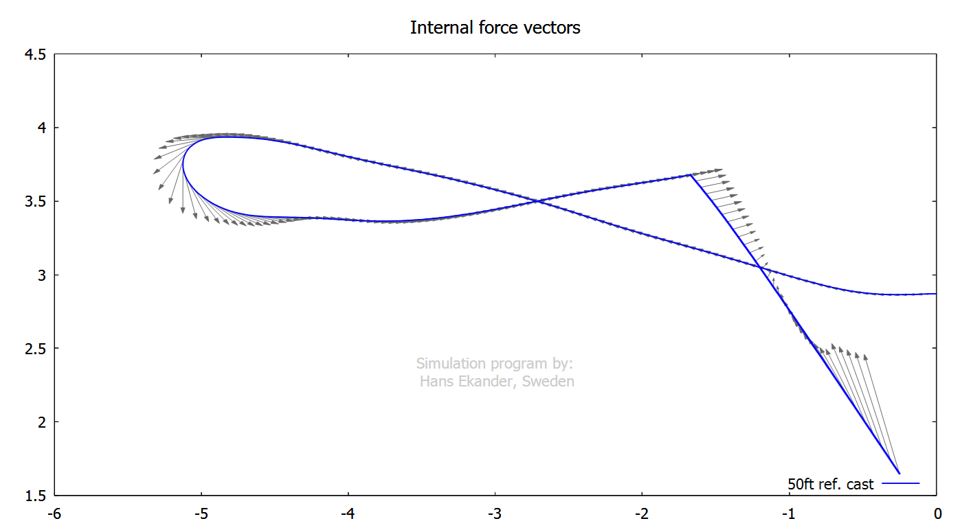
The vector plot below shows the internal
force vectors.
Notation, see also Theory:
Speed A
measure of how fast an object is moving, in units of length/time.
Velocity Speed
in a specific direction, in units of length/time.
Haul velocity Line
speed through the guides toward the rod handle.
Feed velocity Line
speed through the guides toward the rod tip.
Acceleration The
rate of change of the velocity of an object with respect to time.
Angular velocity Velocity of rotation around a point, in units of
angle/time.
Boundary condition Conditions
that are defined/set at either end of the computation domain e.g., at the rod
handle or at the fly.
Young’s modulus Is a
measure of the stiffness of a material defined as stress/strain, in units of
force/area. Stress is the force per unit area and strain is the
elongation/length.
Curvature The
magnitude of the curvature of an element, e.g. the rod or the line, is 1/(radius of curvature), measured units of 1/length.
Bending moment Bending
moment is the reaction induced in a structure, e.g. the rod, when it is loaded
in such a way as to making it bend, measured units of force*length.
Bending stiffness The bending stiffness, here denoted EI,
is a measure of the static resistance of a slender structure, here the rod or
the line, to bend. EI = (bending moment)/curvature.
Mass density Mass
density is measured in units of mass/length. The mass density is the mass of a
very short piece (of rod or line) divided by the length of the very short
piece.